American Society of Civil Engineers
Instituted 1852
Transactions
Paper No. 1128
Walnut Lane Bridge, Philadelphia.*
By George S. Webster and Henry H. Quimby, Members, Am. Soc. C. E.
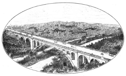
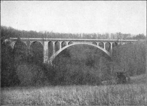
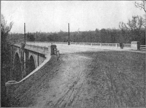
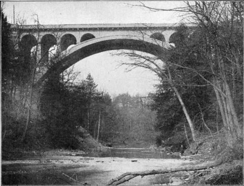
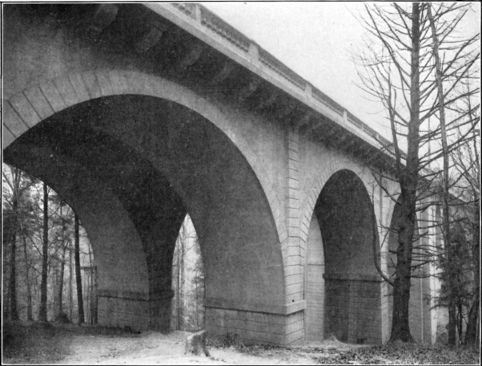
The bridge on the line of Walnut Lane, Philadelphia, over Wissahickon Creek, is notable for the great size of its main arch, for the novelty of some of its features, the character of its material, and the method of its construction. It is hoped that a description of it, with a discussion of the principles of its design, the reasons for its special features, and the lessons learned in the course of its construction will be of interest to the Profession.
The ravine of Wissahickon Creek, in Fairmount Park, is narrow and deep. It separates two populous sections of the City—Germantown and Roxborough—which are both on high ground, and heretofore most of the travel between them has been required to make a long detour, all of the bridges being at a low level and the approaches to them too heavy in grade for business hauling.
By Ordinance of July 13th, 1905, City Councils authorized the construction of a high-level bridge on the line of Walnut Lane, the point where the ravine is narrowest and most advantageous for the crossing.
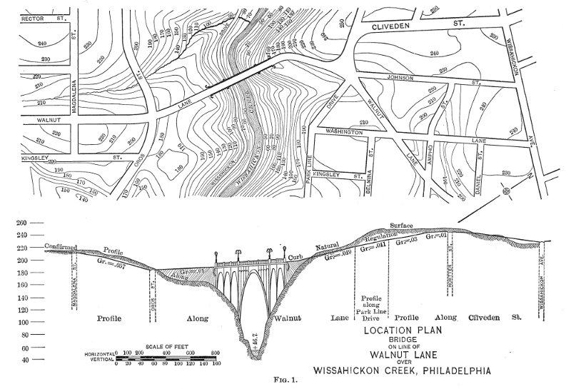
The required length of structure, of course, depended on the elevation of the deck, and as considerable grading of approaches was necessary—cutting for one and filling for the other—the rate of grade to be obtained on the approaches, together with the estimated money value of each percent. of reduced street gradient, entered into the consideration of the problem of dimensions and design. The question was somewhat further involved by the fact that on the Germantown side the approach is from three streets. Fig. 1 exhibits the original profiles and the elevations and grades adopted. A portion of the filling for the west approach was obtained from the cut of the east approach, and was carted across the bridge.
The bridge deck was given an ascending grade to the east—1½% to the middle of the main span and 1% from there to the east abutment. This change of grade was made in order to produce a slight corning and relieve the elevation, or side view of the bridge, of the optical illusion of a dished appearance in the deck over the arch. This crowning is equivalent to a local grade of 1 in 400 on each side.
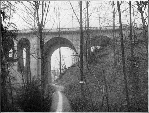
The grades adopted give the floor at the middle an elevation of 147 ft. above ordinary water level in the creek. As the depth of the structure at the crown is 14 ft., the soffit is 133 ft. above the creek and about 103 ft. above the drive, giving an imposing and majestic sweep of arch that is very impressive.
As the two springing points are at the same elevation, the grade over the bridge, in making the spandrel piers on one side higher and therefore thicker, puts extra dead load on that side, and this is counterbalanced by making the walls of the spandrel piers on the other side 4½ in. thicker.
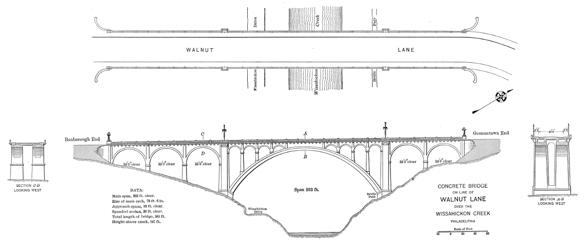
In considering the matter of type of structure and length of spans, it was regarded as very undesirable, for æsthetic reasons, that there should be any pier or column interposed between the creek and the pleasure drive which winds along the west bank at an elevation of about 30 ft. above the water. The situation clearly indicated an arch as the only suitable form of support for the roadway, and the necessity of clearing both the drive and the creek, while making reasonable provision for the future widening of the drive, taken in consideration with the profile of the rocky bluffs, fixed the location of the abutment piers and the span of the main arch, which was made 233 ft. between the vertical faces of the piers.
The extraordinary length of the main span gave to the structure a monumental character, and it became important that the remainder of the design and the material of which the bridge was to be constructed should be in accord with it.
The lowest cost would have been found in a steel viaduct with a wooden floor, but the character of the surroundings—natural park scenery of rocky and wooded slopes—would cause such a structure to appear in appropriate and inadequate, and the possibility of future neglect of proper maintenance enhanced the importance of selecting a construction of the most permanent character.
The development from the sphere of usefulness of concrete, and the city's extended experience in the use of it for arches, walls, and floors, with new and improved methods of manipulation and construction, whereby more nearly uniform character and value are assured ,together with the great economy obtained through its use, influenced the adoption of concrete as the structural material of the bridge throughout, and it was designed so as to require steel reinforcement at only a few places.
The most economical length of the approach spans was determined by trial to be 60 ft. from center to center of the piers, or 53 ft. clear. The conditions called for three of these spans on the west slope and two on the east slope of the ravine.
The profile of the rocky banks naturally fixed the location of the springing points of the main arch, and gave a graceful proportion between the clear height above the creek and the length of the span.
The type of structure selected is that of the stone arch bridge in Luxemburg, Europe, built in 1904, which is substantially two bridges side by side with the space between them floored over. The type is economical for such a structure, because large masonry arches of a width sufficient for their own independent stability have more than ample strength for any highway live load that may have to be carried, and any increase in width or strength would be utilized only in sustaining the weight of the added material. Thus, in the main span of this bridge, the arch ribs themselves constitute one-half of the whole load to be carried—both dead and live—and, as the live load is less than one-twelfth of the dead load, a single barrel of the full width of the floor would clearly be wasteful because its thickness could not safely be made much less than that of the narrow ribs. The width of the floor is 60ft., while that of each of the two ribs is 18 ft.—giving together 36 ft. of supporting arch, or only 60% of the floor width. The space between the ribs is 16 ft., leaving 4 ft. of floor to overhang on each side.
Each of the two halves or ribs of the bridge carries two vertical walls, 2 ft. 6 in. thick, which extend up to and carry the floor. These walls are set in 9 in. from the edges of the ribs, giving an actual overhang of 4 ft. 9 in. to the sidewalk floors on the outside of the bridge.
The three aisles thus formed, and spanned by the floor, are 20 ft. and 14 ft. for the middle and side aisles, respectively, from center to center of the walls.
These longitudinal walls are full spandrels over the 53-ft. arches, but on the main arch they are pierced by four 20-ft. arches over each haunch, leaving 60 ft. blank over the crown. These 20-ft. openings are flanged 6 in., in order to give the barrel or rib of each arch a width of 3 ft. 6 in., and pilasters of equal relief, 2 ft. 10 in. wide, were made between the arches to afford angles for concealing the vertical joints in the wall. In 53-ft. arches the flanging of the walls is 9 in., making the ribs 4 ft. wide, but a sheeting of concrete, 18 in. thick, connects the ribs into pairs constituting the barrels, 18 ft. wide.
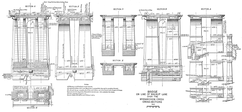
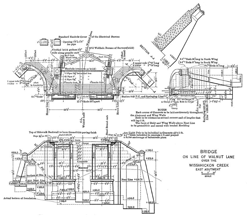
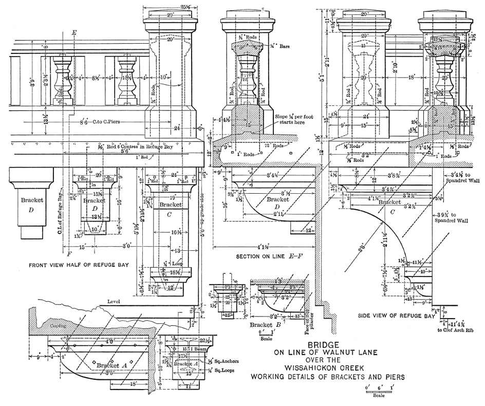
For architectural effect, the abutment piers at the ends of the main arch are widened to project 3 ft. beyond the general line of the structure, and they provide for refuge bays in the sidewalks of the deck. The twin shafts of these piers are hollow, 6 by 10 ft., giving table thickness of wall of 3 ft., which is increased below the water-tables by the pilasters under the arches. They have a floored chamber under the sidewalk, in order to give access to the electrical conduits and the bases of the light poles. The 10-in. vertical wrought-iron drain pipes from the grate-top inlets in the driveway gutters are secured to the inside wall of these shafts, and pass the drainage out through 16-in. cast-iron pipes built into the body of the pier and outletting on the rocky banks of the creek.
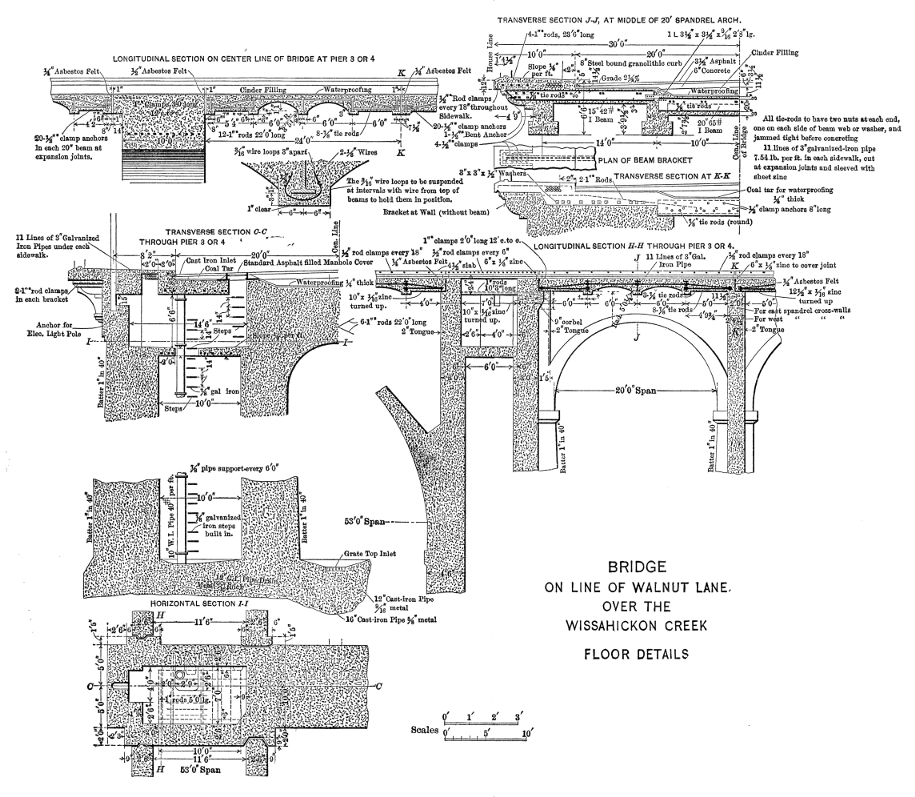
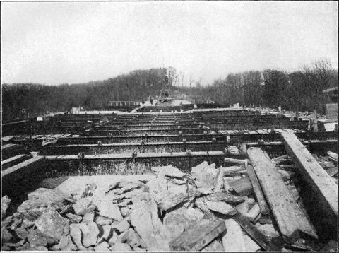
The floor structure consists of transverse rolled-steel I-beams, 6 ft. from center to center, with concrete jack-arches between them. The beams over the 20-ft. middle aisle are 20-in. 65-lb. per ft., and those over the 14-ft. side aisles are 15-in. 42-lb. per ft. The size of the floor members was determined by the assumed concentrated loads adopted as the standard for highway bridges in the City of Philadelphia, which consist of a truck, weighing 40 tons, on four wheels spaced 20 ft. between axles, and 6 ft. gauge, or two street-railway cars side by side, weighing 20 tons on each truck.
The concrete jack-arches can be depended on to distribute an axle load over two or more beams when the axles are more than 6 ft. apart, for a beam cannot deflect under its load without throwing some load on its immediate neighbors. The floor concrete is filled monolithically to 3 in. above the tops of the floor-beams. If the spring of the jack-arch be taken at the lower fillet of the beams, and a centroid of pressure be assumed 1½ in. above the tops of the beams, there is constituted for distributing purposes an arch of 12-ft. span, having a rise equal to the depth of the beam, and an effective thickness of 3 in. at the crown. A further assumption is made that the embedded beam will distribute a concentrated wheel load of 10 tons laterally over a space equal to the gauge of the wheels—6 ft. Each transverse foot of floor arch, therefore, is required to sustain 3 333 lb. of live load, and if one-half of this be distributed to the adjacent beams, the horizontal force developed in the distributing arch will give, in the worst case—that of the 15-in. side aisle beams—a unit of stress of only 112 lb. per sq. in. Thus it appears unnecessary to compute the beams for more than one-half of an axle load when the axles are 12 ft. or more apart, but the standard weight of the beams used gives value equivalent to five-eights of the 20-ton axle load at a fiber stress of 15 000 lb., without allowance for the reinforcing value of the encasing concrete. As it is found by experiment, confirming calculations based on conservative assumptions of adhesion of the concrete to the steel, that the embedment of rolled beams in concrete adds one-third to their carrying capacity, the margin possessed by the floor to carry heavier live loads than those specified is so great that the live load may be doubled without stressing the steel beyond common practice. The construction proves to be very rigid under rolling loads.
Careful estimates were made of the relative cost of floor construction of this type and of reinforced concrete—concrete beams and slabs reinforced with steel bars. The latter appeared to be the lower in cost by about $4.60 per panel, or less than $1 per lin. ft. of bridge, but at that time experience with construction of that class, for the severe service of heavy street traffic, was limited, and it was felt that the steel beams with independent strength were less of an experiment, and besides, the beams would furnish support for the forms of the floor arches. As these forms were required to be carried high in the air, the support afforded by the beams, and consequently the lesser cost of scaffolding, doubtless quite offset the higher cost of the material.
The 15-in. beams and the 20-in. beams in line with them were firmly connected by heavy angle irons with four
| 15 |
| 16 |
All the beams are completely encased in concrete, which is 3 in. thick over the top surface and around the bottom flanges. At the latter point,
| 3 |
| 16 |
The floor over the middle aisle is depressed to permit the use of wooden ties and cinder ballast for two street-railway tracks, and to afford also, if it should ever be required, depth for an underground trolley conduit.
The whole of the driveway floor surface below the paving is water-proofed with a coating of coal-tar roofing pitch, from
| 1 |
| 8 |
The depression is filled with cinders, over which is laid the 6-in. concrete paving base. The driveway, 40 ft. wide between curbs, is paved with asphalt, and the two sidewalks, 8 ft. 3 in. wide, are granolithic with steel-edged curbs.
The 2½-ft. longitudinal walls are connected at intervals over the piers an dribs of the approach arches, and over the ribs of the main arch, by 24-in. cross-walls, which serve as braces for the walls and as diaphragms or transverse bracing to transmit to the arch ribs the wind forces on the floor. The floor is separated by joints into sections to localize the contraction, and the interruption of its continuity prevents its action as a horizontal beam to transmit the wind stress to the main piers. Each section, therefore, is required to transmit its horizontal forces to the arch ribs. To provide the requisite stability in the long slender ribs of the main arch, they are flared 1 ft. 9 in. on each face, from the crown to the spring, increasing the width from 18 ft. at the crown to 21 ft. 6 in. at the spring. This flaring corresponds to a vertical batter on each face of 1 in 40 a projected cross-section, and the edges of the ribs, therefore, are in planes parallel to and almost coinciding with the battered faces of the piers. It also causes a slight but not noticeable warp in the face surface, the ribs being made rectangular in section at every point in a radial direction. The thickness of the ring is 9 ft. 6 in. at the spring and 5 ft. 6 in. at the crown. The ribs of the approach spans are not flared—the width being 18 ft. throughout—and their faces are plumb.
The transverse walls do not extend of the space between the ribs, the latter being independent of each other, but the shafts of the piers at the ends of the main arch are connected by a transverse arch of 12 ft. clear span and 10 ft. wide, having embedded in it twelve 1-in. square steel bars diagonally crossed to act as transverse bracing for the shafts. The transverse walls on the ribs are 2 ft. thick throughout the bridge, except those over the west half of the main arch where they were increased in thickness to 2 ft. 4½ in., in order to provide sufficient weight to make the dead load on the arch symmetrical by counter-balancing the heavier load on the east half caused by the greater height of the spandrel piers due to the ascending grade over the bridge.
The abutments were especially designed to economize material and at the same time avoid too utilitarian an appearance. The thrust of the end arch ribs is utilized to balance the earth pressure; and the curvature of the wings, besides embellishing the structure, has the effect of broadening the foundation and thus giving the equivalent of a much thicker wall to resist overturning. This effect is increased by the construction of a buttress, 4 ft. thick, at the extreme end of the wing in a direction radial to the curve, or at an angle of 45° with the axis of the bridge. At the junction of the wings and the front wall, steel rods are embedded for the double purpose of giving cantilever value to the projecting wings, and preventing vertical cracks in the sharp re-entrant angles of the corners. Some of these rods are continued in a straight line past the middle of the curve of the wing and within 6 in. of the surface, in order to give, if it should be required, beam value to the wing between the abutment wall and the buttress at the end of the wing.
The east abutment is 64 ft. high, from foundation to coping, about 38 ft. of this being above the natural surface of the ground in front of it. The south wing of this abutment is built around a 30-in. water main, a hole 6 ft. in diameter being made in the wing to give free access to all sides of the pipe for repairs. The foundations of all the piers were required to be constructed over this pipe, and in each case an arch was formed over it to give 18 in. clear space around it, steel rods being embedded over the openings to resist any tendency to crack. The foundation of Pier 4 was extended because the pipe arch was near the end of the pier.
All piers, abutments, and wings, were founded on solid rock, the surface of which was found to be extremely rugged, requiring no stepping. In the foundations of each of the main arch piers two drill holes were sunk 8 ft. below the bottom to make sure of the solidity of the rock, and no crevices were found. The rock is a mica schist.
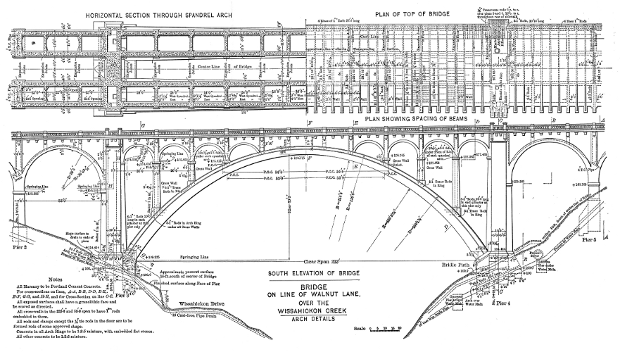
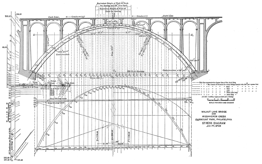
The open character of the spandrels on the main arch, with their numerous vertical joints, presented a condition quite different from that commonly found with solid spandrels of rigid walls and earth filling, where the load is distributed and the tendency to buck up is met with concentrated resistance. Here, the loads, except immediately over the crown, are all concentrated, and there is no stiffness in either walls or floor to concentrate resistance to buckling. Each panel delivers its own individual load, dead and live, at the same point always, and resists to only the same amount. The long ring rib, therefore, acts as a column, square-ended, throated in the middle, subject to varying eccentric loads, and made up of blocks accurately fitted together but not adhering, and, consequently, it is dependent for its ability entirely on its sufficiency of thickness to accommodate the varying center of pressure. Therefore, it became specially important to determine the extreme eccentricity of the pressure line by trying every possible condition of loading, both concentrated and distributed. The effects of six different conditions are shown by the stress diagram, Plate XXVIII. The shape adopted for the arch is an intermediate between the extremes of eccentricity, coinciding very nearly with the line of dead or constant loading, with a slight arbitrary allowance at the spring for possible initial stress in the intrados from any shrinkage or settlement which might take place after keying, or from being keyed at a temperature above mean, as seemed likely to be the case. This shape was obtained by compounding segmental curves on three centers for each surface, as shown on Plates XVII and XXVIII.
The arch was made square-ended, and continuous at the crown, in preference to hinging it. While pivotal bearings at the three points would have eliminated temperature stresses from falsework settlement, the cost would have been greater, and far less graceful lines would have resulted. The line of center pressure, if confined to pivots at springs and crown, would depart far from the mid-line of the ring at the quarters and require considerably greater thickness there than is needed with the flat-end bearing. The continuous taper in thickness as well as width of rib, from the abutments to the crown, is an important element of beauty in the design. In further pursuit of lightness in the appearance of the ring, a simple moulding was constructed on the outer face of each rib, tapering in width in proportion to the thickness of the ring.
The span of the arch, from center to center of bearings on the skewbacks, is 240 ft., and the rise of the mid-line of 70.5 ft.
The maximum fiber stress appears to be at the spring, where there is the greatest theoretical eccentricity, because of the arbitrary allowance made for initial stress. The maximum is 380 lb. per sq. in., and the average at the same point is 240 lb.
The temperature stresses were computed in two ways, the results corresponding fairly. One method was by using the ordinary deflection formula for beams, and the other was by calculating the increase and decrease in length of extrados and intrados on the curvature resulting from the change in length of the ring and its confinement at the ends, the changes in length of fiber representing stress assumed to be in proportion to a modulus of elasticity of 2 000 000 in both compression and tension. Computations were based on a change of the general temperature of the arch of 40° Fahr., either way from the temperature at keying, which will change the length of the arch 1 in. and cause a change of 1 in. in the elevation of the crown. A rise increases the curvature at the crown, shortening its radius, and—because of the fixed ends—decreases the curvature of the haunches, lengthening the radius. This produced compression of the intrados at the crown—maximum at the middle—and of the extrados at the haunches—maximum at the spring—the effect being zero at the point of contra-flexure. This point was assumed to be at the K line of the stress diagram, Plate XXVIII, which was computed by the Cain method, 82 ft. from the spring, and the substantial correctness of the locality was demonstrated by the close agreement of the bending stresses in the several divisions, the deformation of the arch being necessarily an automatic adjustment of the shape to produce uniformity of fiber stress in bending.
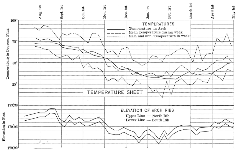
Measurements of the changes in elevation of the crown since the completion of the arch show a total difference between the extremes of winter and summer of 1
| 1 |
| 8 |
| 1 |
| 8 |
Some time after the completion of the arch rings, an electric resistance thermometer, of the standard type made by Leeds and Northrup, was embedded in one of the ribs on the mid-line near the spring, and weekly observations were made of the temperature of the heart of the concrete. A diagram showing the results of the changes in temperature and in the elevation of the crown of the arch is shown on Fig. 2. The heavy upper line gives the actual temperature in the arch; the dotted lines show the maximum, minimum, and mean weekly temperatures, as given by the United States Weather Bureau station in Philadelphia. The solid lower lines indicate the elevation of the two arch ribs. It will be observed that the total change of temperature in the center of the arch amounts to 42.8° Fahr., which gives a close check on both the assumptions used in the design, and on the computations of temperature changes made from the change in elevation. The close relation between the various curves in the diagram is also evident.
The concrete of the structure was of several classes, but in all classes—foundations, piers, abutments, walls, and balustrades—stones of as large size as conveniently workable were embedded. Some derrick stones were used in the foundations, but did not appear to be economical, because, under the specifications, a sufficient depth of concrete was required to be in place to half embed the stone, and it was found impracticable to get in as large a volume of embedded stone as by the use of one-man size. Besides, the monopoly of a derrick, during the time of placing a large stone, delayed the delivery of material and reduced the yardage of work accomplished. The quantity of stone thus embedded varied in different portions of the work, according to circumstances—the consistence of the concrete, the character of the sand and coarse aggregate, the convenience of location, and the skill of the workmen. Observations of the relative quantities of stone and mixer concrete used have determined that in horizontal courses, such as are laid in piers and walls, the embedded stone constitutes from 30 to 40% of the total volume of the finished work, depending on the shape of the stone and the efforts of the laborers. The percentage secured in the arch, where all the tones were required to be placed radially, was from 25 to 30. The contractors were encouraged to use as large a percentage as could be embedded and fully flushed in the concrete, and they were of course desirous of using as much as possible, because its cost was less than that of the concrete displaced by it.
The use of this embedded stone is found to be economical in about all classes of concrete work, even such as is reinforced with steel rods. Of course, care must be taken in reinforced work that stones do not ride upon rods in a manner to permit the format of voids under the stones. The increase in compressive strength of all classes of concrete obtained by the embedment of large stones, as indicated by the tests of cubes, enhances the value of the material for almost if not quite all classes of work. The stones also very materially increase the shearing strength of the concrete, and generally reduce its cost.
The concrete of the ring of each 53-ft. arch was deposited continuously, was accomplished always in one day or less, and is of the same character and quality as that in the main arch—1:2:5 mixer concrete with flat stone embedded radially. The skewback was formed at the point of meeting of the arch ring with the transverse walls on the piers, the portion of the arch below this—called the umbrella—being constructed as a part of the pier.
The arches of this bridge, as constructed of this composite material, may be regarded as stone arches of a grade of workmanship superior to the ordinary rubble arch, because of the complete bedding of the individual stones. The increased compressive strength obtained by the embedment of the stone is attended, of course, with a considerable increase in the shearing resistance, and this quality is valued in consideration of the forces operating in the arch at the skewback, where eccentricity of direct stress produces actual shearing stress. The main arch ribs are practically columns, with more or less eccentric loading, and varying and somewhat indefinite intensity of bearing stress at the ends. Concrete prisms or columns, when compressed to destruction, usually fail by shear, the angle approximating 39° with the axis of compression, and a force acting at any angle to the direction of the compression that causes the shearing will constitute a shearing force and hasten the failure. Such an angular force is produced by eccentricity of direct stress or by increments of loading and own weight. Tests of concrete model arches, made in order to determine questions of design, indicated that it is wise to treat the components of the direct arch stress at the abutment as so much shear acting in a beam. Regarded as such, the vertical component or reaction at the spring of the main arch ribs of this bridge amounts to 108 lb. per sq. in. of arch section in shear at the face of the skewback, which would be high for simple concrete, but is allowable for the hybrid material.
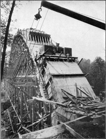
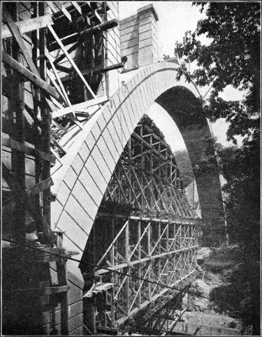
| 
|
| Fig. 1—Washing the Surface of the Arch. | Fig. 2—South Rib, Walnut Lane Bridge, after Removal of Centering. |
The mix of concrete used in the foundations and in the body of the piers and walls was 1 part Portland cement, 3 parts sand and 6 parts crushed stone. In the arches—the main and approach ribs and floor jack-arches—the mix was 1:2:5. The facing concrete or granolithic mixture of all showing surfaces, and also the body of the balustrade work was 1:2:3. It was all mixed so mushy that the large stone could easily be submerged in it by joggling.
The sand was required to be graded—grains varying from fine to coarse—and a yellow bank sand from New Jersey was accepted and used. Crushed stone was required to be graded in size from ¼ in. up, limited to 1½ in. generally, and to ¾ in. for arch and floor work. After using the 1½-in. size for a time the contractor preferred to use a 1-in. size limit because of the greater facility which it seemed to provide for embedding the large stone. The difficulty, however, with the 1½-in. stone was in obtaining a satisfactory grading—a proper admixture of all sizes from ¼ in. up—the practice of the quarries generally being to separate the 1½-in. stone from the smaller size. If, however, the run of the crusher up to the 1½-in. size can be obtained, the larger size will give equally satisfactory results and perhaps somewhat better concrete. The most thoroughly graded aggregate is found to produce, not only the densest and strongest concrete, but the smoothest working.
Every car lot of cement received was sampled after delivery at the work, and was tested in the municipal laboratory before being used. It was required to meet the standard specifications of the Bureau of Surveys of the City of Philadelphia, which are as follows:
"The acceptance or rejection of a cement to be used shall rest with the Chief Engineer, and will be based on the following requirements:
"Specific gravity not less than 3.1.
"Ultimate tensile strength:
"Fineness:
Residue on No. 100 sieve not over 8 per cent. by weight.
Residue on No. 2200 sieve not over 25 per cent. by weight."Set: It shall require at least 20 minutes to develop initial set, and shall develop hard set in not less than 1 hour nor more than 10 hours. These requirements may be modified where the conditions of use make it desirable.
"Consistency of Volume: Pats of cement 3 inches in diameter, one-half inch thick at center, tapering to thin edge, immersed in water after 24 hours in moist air, shall show no signs of cracking, distortion or disintegration. Similar pats in air shall also remain sound and hard. The cement shall pass such accelerated tests as the Chief Engineer may determine.
"Sulphuric anhydride (SO3); not more than 1.75 per cent.
"Magnesia (MgO); not more than 4 per cent.
"Briquettes for testing shall be 1 sq. in. area of cross-section; sieves shall be of brass wire-cloth having approximately 9 800 and 37 500 meshes per square inch, respectively, the diameter of the wire being 0.045 and 0.023, respectively."
The accelerated test used consisted in making a small ball of neat cement paste, allowing it to harden 24 hours in moist air, and then boiling it for 3 hours.
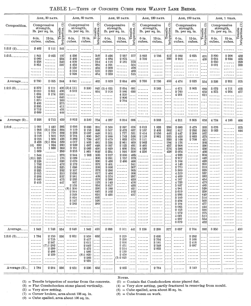
For purposes of record and comparison, specimen 6-in. and 12in. cubes of concrete, as taken from the mixer, were made by the inspectors at frequent intervals during the progress of the work, and tested in the city's laboratory. Standard briquettes were also made by the inspectors from the mortar extracted from the concrete. Table 1 shows the results of tests of both cubes and briquettes. A number of the cubes had embedded flat stones representing as nearly as practicable the character of the concrete made in the work.
It will be observed that:
(1.) The 12-in. cubes have a strength of about 80% of the 6-in. cubes;
(2.) The 12-in. cubes containing large stones embedded in them average from 25 to 35% stronger than plain cubes;
(3.) The strength of the concrete shows a fairly regular increase with age;
(4.) The strength of the 6-months old concrete may be assumed to be at least 2 000 lb. per sq. in.
The crushed stone used in the early part of the work and throughout the construction of the first main arch rib was a very hard black shale of high shearing strength and well graded in size, but was so sharply angular that it was gritty in the concrete and was thought to be less smooth working than limestone. Accordingly, a change was made to crushed limestone, with very satisfactory results. The comparison and properties of these stones were as follows:
| Limestone. | Black shale. | |||
|---|---|---|---|---|
| Composition: | { | Passing No. 10 sieve ......... | 1.9% | 1.5% |
| " ¼-in. sieve ....... | 15.5% | 12.5% | ||
| " ½-" " ....... | 44.6% | 34.7% | ||
| " ¾-" " ....... | 77.6% | 70.4% | ||
| " 1-" " ....... | 96.8% | 94.8% | ||
| Retained on 1=" " ....... | 3.2% | 5.2% | ||
| Weight per cubic foot......... | 98.9 lb. | 90.9 lb. | ||
| Specific gravity............... | 2.84 | 2.66 | ||
| Percentage of voids........... | 44.1 | 45.1 |
The embedded stone used throughout the work is known as "Conshohocken" stone—a laminated silicous rock of very high compressive strength—which comes from the quarry in flat shape and with tapering edges, which facilitated the embedment of the stones in a radial direction in the arch rings, and permitted close packing with good bonding in the horizontal courses of the piers, etc.
The showing faces of the concrete throughout the bridge were made with a fine concrete or granolithic mixture, using for all except the balustrades a crushed black shale which had passed a
| 3 |
| 8 |
This process of finishing produces a surface which very closely resembles stone in texture, and, as it removes the cement film which segregates against the forms, all likelihood of surface cracking is eliminated. The tone or color of the surface, of course, depends on the aggregate used in the facing mortar. The black shale grit and the yellow bank sand used for facing the body of this bridge produce the general color and tone of Eastern granite. The mixture used in the construction of the balustrades, which constituted both the body and the face, was made with crushed granite screenings in place of the black shale grit used in the remainder of the work, and a pleasing contrast in tone was thereby obtained.
The use of this fine concrete for surfacing was for the twofold purpose of obtaining a more durable material, it being richer in cement, and a more uniform texture than would result from washing a concrete of coarser aggregate.
To facilitate the removal of the forms for finishing the surface, they were constructed with the uprights or studs set about 8 in. from the face of the work, and the planks of the forms, which were in width equal to the depth of the courses, were secured in place with easily removable cleats tacked to the uprights. On the top and bottom edges of the planks were fastened bead strips, 2½ in. wide, projecting beyond the planks into the concrete to cause imprints. Courses were finished at the apex of the top bead, and, when the forms and planks were removed on the following day to permit the washing of the surface, they were raised one course, so that the bottom bead fitted into the half imprint left by the top bead. The work was thus built up course by course, in the smaller portions several courses being laid at one operation. No vertical beads were used, and no effort was made to imitate ashlar stone construction.
As the soffits of the arches could not be exposed for washing until the centers were removed, and the surface was then too hard to be removed by a brush, the impression of the lagging was removed by tool dressing. Pneumatic bush-hammers were used from the swinging scaffold, and the work was done before the floor was laid, so that the scaffold could be supported from out-looker timbers on top of the spandrel walls.
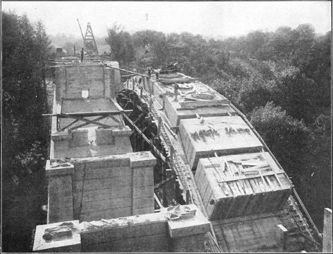
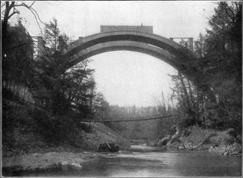
The construction of the main arch ribs was by blocks or voussoirs of a size limited to 75 cu. yd. each, always in pairs simultaneously—one on each side—so that the horizontal thrusting effect on the centering would be kept balanced.
The specifications prescribed that each section or block was to be constructed continuously from start to finish without cessation, in order to avoid joints, but in several cases it was found to be impossible to complete the section before dark, and forms were then erected to give to the day's work a radial face. Generally, it was found possible to complete a pair of blocks within daylight of one day—an output of about 150 cu. yd.
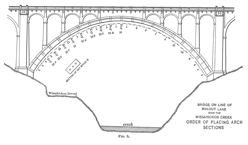
The number of large blocks was twenty-two—in eleven pairs—placed in the order of their numbers as shown by Fig. 3, with seventeen small blocks or keys. The first two cast were adjacent to the crown key, thus reversing the usual order of procedure in the construction of masonry arches, although it has been customary to weight down arch centers at the middle with a temporary load to prevent the rising at the crown caused by the thrust of the arch at the haunches. The arrangement was such as to leave seventeen small spaces for keying, the size of these spaces varying from 2 ft. 6 in. for the lower key to 2 ft. 0 in for the crown key.
The method of construction used—building the voussoirs independently, scattered over the centering, to be joined later by the keys—required extreme care in the building of the forms, but the work was done very accurately, and all the edges of the ribs are in good line, and are entirely without kinks or waves.
The purpose of this method of construction was to distribute the load over the centering and permit the centering to attain its maximum deformation before key, in order to prevent the occurrence of cracks in the arch, a condition which has generally been experienced in the construction of both stone and concrete arches under the usual method of beginning at the spring and proceeding continuously up to and keying at the crown. The utility of the method was demonstrated long before the completion of the first ring. It proved to be entirely successful, and although each main arch rib has in it forty joints, there has not yet been discovered any disposition to open anywhere as the result either of loading or of temperature changes.
Some of the individual voussoir blocks on the steeper portions of the centering were required to be secured against sliding down hill on the lagging. This was accomplished in the case of the third pair of blocks—which were at the quarter points—by means of three 1¼-in., round, upset rods, made up to the required length with turnbuckles, and having 12 by 12 by
| 7 |
| 8 |
| 1 |
| 32 |
The anticipated hinge action of these struts developed as the load on the center increased, and it was demonstrated by their progressive cracking as the successive blocks were cast. The crack in each case opened on the upper or outer side of the struts, extending generally to within 6 in. of the under side, thus reducing the actual area for service to a fraction of what was provided, but it was evidently ample for the actual requirements. No special effort was made to grout up these openings, and any failure of the liquid of the concrete to penetrate and fill them would of course leave some small portion of the arch section unflushed and void, but the area thus lost was trifling, and, moreover, was at the least important part of the arch—the mid-line.
The theory of the construction of this arch, involving the principle of numerous keys and temporary hinges, logically called for a key space at the springing line, but it was omitted there because the satisfactory construction of a key would have been difficult, and the struts necessary for maintaining the space during the construction of the remainder of the arch would have been large enough to interfere somewhat with the proper deposit and compacting of the concrete of the body beneath the struts. The three lower blocks, therefore—Blocks 2, 4, and 6, Fig. 2—were cast in contact, and thus formed practically one section about 25 ft. long, directly on the skewback and with its center of gravity about 4 ft. in front of the face of the abutment. The correctness of the theory referred to—that a key was necessary at the spring—was demonstrated when Block 8 was cast. The pressure on the falsework, at this stage of the construction, caused sufficient yielding of the centering to permit the heavy 25-ft. section to tilt forward and separate from the skewback at the outer side while bearing on the inner or lower edge. This action occurred at all four of the skewbacks, the cracks thus formed varying in size of opening from
| 1 |
| 8 |
| 3 |
| 8 |
As the construction of the arch on the sections as tilted would have concentrated all the arch pressure on a fraction of the area of the ring at the skewback, it was necessary to push these sections back until their bearing was uniform over the whole width of the skewback. This was accomplished with screw-jacks and wedges acting under the joists and against the horizontal timbers of the falsework, and it is believed that, because of this adjustment, practically all initial stress in the arch ring was avoided. The distribution of the voussoir blocks over the centering, before constructing any of the keys, gave to the falsework almost all its load, and produced the maximum deformation in it before the keys closed the ring. The entire absence of openings in any of the joints between keys and sections, and of any cracks in the sections at any subsequent stage of the erection, is proof of the fact that the line of pressure was always within the middle third of the depth of the ring, for none of the joints have any tensile resistance to opening.
One of the ribs was subjected to an unintentional but interesting test of its stability by inadvertent unsymmetrical loading during the construction of the spandrel walls, which work was done after the centering had been removed. The work of construction over the arch was required to be carried on simultaneously on opposite sides, in order to avoid unsymmetrical loading, but, through a combination of circumstances, the rule was neglected for a part of a day, and a weight of about 100 tons of concrete was deposited in the spandrel walls of one section immediately over one of the quarters without any balancing load on the opposite quarter. As soon as the condition was discovered a careful examination was made of all the joints of the arch, but not the slightest evidence of distortion could be perceived. A pressure diagram, covering this condition, was made subsequently, and the center of pressure was found to be within the middle third of the arch ring. This is accounted for by the great weight of the arch ring itself.
The centering was required to be maintained under the completed arch ring for at least one month. The first ring was keyed in a season of rising temperature (June 7th), and the wedges of the centering were struck one month later. The second arch was keyed in cool weather (October 17th), and the support was continued for 6 weeks. The stresses in the woodwork were high enough, apparently, to produce progressive deflection, so that, during the time of loading and subsequent seasoning, the falsework compressed sufficiently to lower the crown 3¾ in., this amount being the same for both ribs. In anticipation of this compression, the centering was originally set higher than the plan elevation. During the construction of the keys the woodwork was saturated with water as far as practicable by flowing water upon the bents through holes in the lagging, and the water was shut off as soon as the keys were completed, the purpose being to obtain the advantage of the shrinkage of the wood in drying out to withdraw gradually from the arch some of the support of the centering, and thereby facilitate the striking of the wedges. The utility of this process is doubtful when as high stresses are put in the wood as was done in this case, for it is probable that the softening of the unconfined fibers of the wood by the absorption of water did not operate to increase the height of the centering by the swelling of the wood, as was expected. The action of the wood during the period following the keying of the arch, apparently, was the continued yielding under the load, indicating that the elastic resistance was less than the imposed stress, and, as the deflection of the crown of each of the two main ribs was only
| 1 |
| 8 |
| 1 |
| 8 |
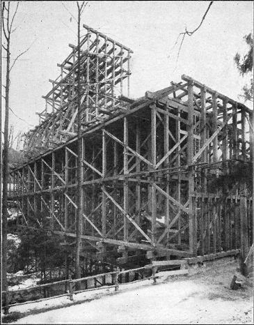
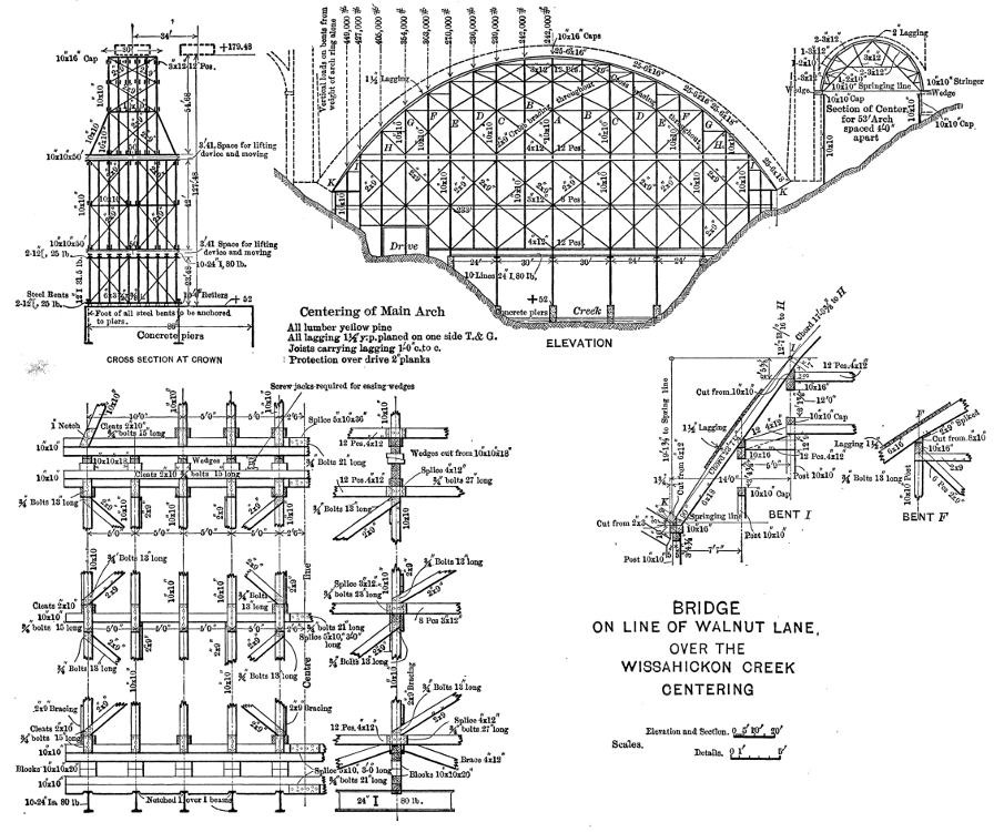
The centering was designed by the contractors. Its general arrangement and details, with stresses and sizes, are shown on Plate XXVII. All bents were supported on concrete piers built on the rock, with the exception of four intermediate ones, which were supported on 24-in. I-beam stringers spanning the creek bays. The lower story of the high bents was made of steel beams and channels braced with angles. The remainder was of yellow pine timber. The working stress in the 10 by 10-in. posts, which had up to 13 diameters of unsupported length, was about 1000 lb. per sq. in. As the sills, blocking, and wedges, were all 10 in. wide, the area of side-grain bearing was the same as the end grain, and the unit stress, therefore, was the same. The resulting crushing of the fibers of the yellow pine sills Where they bore on the 10-in. oak wedges clearly showed that the stress was beyond the proper working load for side-grain bearing. The extreme fiber stress in bending on joists and on caps of bents was 1 200 lb. per sq. in., and ample strength and stiffness in these members was evident. The steel I-beam stringers were stressed at 16 000 lb. per sq. in., and the resulting deflection, therefore, was normal, and had no effect on the concrete work. The steel I-beam posts of the lower story had. a stress of from 5 700 to 8 500 lb. per sq. in., according to the unsupported length between points of attachment of the diagonal bracing. The 6-in. steel rollers under the high bents were loaded, during the erection of the arch, to 3 400 lb. per lin. in., assuming that the rollers were all equally loaded, which is hardly possible. The total weight of the falsework on the rollers of the middle bent was 100 tons.
A peculiar feature of the structure was the method of connecting the curved joists. There were twenty-five lines of these, lapping at each bent and pinned together there with 3-in. round oak treenails. Instead of being notched to bear vertically on the caps of the bents, the joists were left straight and smooth on their underside, and beveled timbers on top of the caps of the bents were dressed to fit under them and receive their pressure. This construction produced horizontal as well as vertical forces to be resisted. In the lower bents the lateral thrust was greater than the vertical because of the steep inclination, and it was resisted by horizontal struts or rangers extending clear across. At the higher bents, where the inclination was flatter, the horizontal effect of the joist bearing was taken up by plank chocks spiked to the joists above and against the beveled timbers.
The designer assumed that the pinning of the joists would cause them to act as an arch and thus carry a considerable portion of the weight of the concrete ribs. It was apparent, however, that they did not act in this way, and also that the lagging did not arch. The length of are was about 280 ft. and the shrinkage of the lagging in drying out was more than sufficient to accommodate the shortening of the arc in the lowering of the crown by the compression of the centering, and, although the joists were very carefully bored for the treenail pins, the play in the holes and the compression of the fibers was evidently sufficient to prevent any observable arching. The placing of the joists was commenced at the crown and proceeded downward on both sides, the lower joists being fitted into the end spaces, the tendency of the joists to slip down being resisted by their linking over the crown, whereby the chain of joists was in tension before the lowering of the centering began. The proportion of rise to span is such that a change in length of arc produces almost exactly the same amount of change in the elevation of the crown. Therefore, for the deflection of 3¾ in. at the crown, the line of joists must have shortened 3¾ in., and, as the end bents depressed
| 1 |
| 8 |
| 3 |
| 16 |
It seems probable that a much stiffer and somewhat more economical structure would have resulted from fitting the ends of the joists and abutting them.
An unsatisfactory detail appeared, also, in the high blocking used between the first and second stories, and between the second and third stories. The caps and sills of the bents at these points were made double, to furnish stiffness between the posts for anticipated jacking, and 20 in. of space was then provided for the jacks. This space, therefore, had to be made up in blocking. Between the first and second stories, two 10 by 10 by 20-in. blocks were used, and between the second and third stories one 10 by 10-in. block and two oak wedges 10 in. wide and 5 in. thick at mid-point. There was thus 60 in. of wood bearing across the fiber, made up of six pieces 10 in. wide. Its objectionable nature appeared in the unsymmetrical yielding of the wood under long-continued pressure, causing the pile of blocks to buckle and begin to topple. No actual failure occurred at any point, but it was evident that if the structure had been required to sustain its maximum load much longer some of the piles of blocks would have collapsed. The unsymmetrical yielding seemed to be due, at least in some cases, to an excess of sap wood on one side of the block—the heart of the wood not being in the center of the stick. In some instances the sap wood split away from the heart wood, having swelled more than the heart wood, probably from absorption of water, and then buckled away.
It was observed that in the higher bents the caps became dished, on account of the greater compression of the interior posts. The concavity was as much as 1½ in., and the soft of the arch rib at the crown, therefore, is necessarily that much curved, and the arch is that much thicker in the middle than at the faces. This dishing was not perceptible in the sills of the second story, and only slightly in the sills and caps between the second and top story, the transverse bracing probably acting to distribute much of the load to the outer posts. The action of the falsework indicated that the unit stresses to which the wood was subjected, in side-grain bearing at least, were beyond its elastic resistance, and it is recommended, therefore, that the working stresses of wood in side-grain bearing, even for temporary duty, should be limited to 500 lb. per sq. in., and that the details should be made as compact as possible.
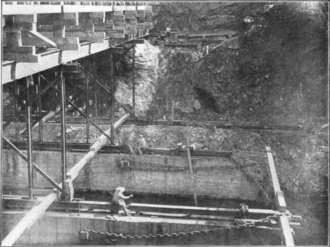
The means provided for adjusting the height of the bents, and for lowering them in striking the center, consisted of oak wedges, 10 in. wide and 20 in. long, tapering from 7 to 3 in. in thickness, placed crosswise of the sills in order to facilitate driving. When the center was lowered the wedges on the end bents at the skewbacks were loosened first by backing them out with sledges. At each of the four points they were found to have only a moderate pressure on them, proving that there was no considerable arch action on either the lagging or the joists. Then the wedges under the middle bent were slackened by backing them only enough to release a portion of the pressure, and successively all the others—working two gangs of men, one toward each end. A number of the wedges were so tightly held that they could not be started without having the weight on them partly taken up on jacks, one or two 15-ton ratchet screw-jacks being used for each tenacious wedge. One wedge refused to budge, even then, and. it had to be split out with chisel bars. The evidently unequal loads carried by different posts of the same bent may be accounted for by different resisting values in the posts, and the consequent deflection and concentration of load by the caps of the bents. After all the wedges had been partially backed, the operation was repeated from the middle bent to the ends, and all bents were lowered several inches clear of the arch. The longitudinal bracing of the bents acted as a truss, and carried the middle bents when their wedges were dropped, thus preventing any bents from lowering much below their immediate neighbors. Notwithstanding the apparently heavy pressure on some of the wedges, it was clear that, at the time of striking, the centering was carrying only a fraction of the weight of the concrete arch, for the deflection of the latter, upon the withdrawal of the support of the centering, amounted to only
| 1 |
| 8 |
| 1 |
| 16 |
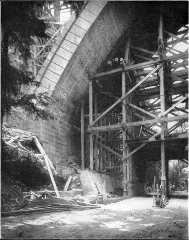
Fig. 1—End of Centering Partly Moved, Walnut Lane Bridge. |
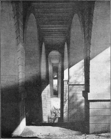
Fig. 2—View Between Ribs, Walnut Lane Bridge. |
One of the reasons for the economy found in the double-rib type of arch was the practicability of building one rib at a time, requiring only enough centering for one rib. Therefore the centering for the main arch was made for a single rib, while the falsework piers were made long enough for the two, and, after the first rib was swung, the whole center—with the exception of the end bents, which were moved independently—was moved over as a unit into position for the second rib. This was accomplished by using rollers under the bents, and jacks pushing on the sills (Fig. 1, Plate XX). The steel bents had been erected on 6-in. solid steel rollers, and 3-in. wood rollers were inserted under the low bents. The jacks heeled against blocks chained to wooden spurs built into the piers for the purpose. The jacks were all actuated simultaneously, and a uniform speed of movement was maintained in order to prevent any skewing of the structure. This operation occupied less than three days.
The centering for the 53-ft. arches was an A-frame truss with a collar tie at mid-height, but no tie at the heels; the thrust, therefore, was sustained by the piers. Computation of the dead weight resistance of the piers to overturning indicated that in two cases it was scarcely equal to the overturning moment, and that prudence would dictate the precaution of ties at the heels of the ribs. They were not used, however, and the construction was accomplished without any visible effect of thrust upon the piers. The dowelling of the courses of the concrete masonry of the piers, which was the result of finishing every course with the embedded stone projecting above the surface, is doubtless to be credited with increasing the resisting moment of the piers by giving tensile value to the joints between the courses.
The vertical support of the trusses of the 53-ft. arch centering was obtained on the 6-in. projection of the coping, supplemented with a wooden trestle bent from the ground up in front of each of the low piers, and, in the case of the high piers, a timber corbel bolted to the face of the concrete. The bolts for the purpose of supporting the form timbers, wherever used throughout the work, were 2 in. in diameter, and built into the concrete; and the nuts, 4 in. square and 9 in. thick, were embedded from 6 to 8 in. As a rule, they were loosened slightly by unscrewing them one turn within a day or two after placing, in order to facilitate their ultimate removal, which was generally accomplished with little trouble. A few, however, were found to be gripped so tightly by the concrete that they were twisted off in the effort to unscrew them from the nuts, and had to be cut off with a chisel. This was done 1 in. or more below the surface, in order to permit a sufficient body of pointing to prevent the metal from rusting and staining the face. All holes left by these bolts were plugged with granolithic mortar and washed to match the face work.
The centers for the 20-ft. spandrel arches were built up and the lagging was nailed on before placing them in position, each center being handled and set as a unit. These were supported on the projecting caps of the piers.
The centering for the Hoar arches was suspended from the embedded steel beams with ¾-in. loop hangers or saddles over the tops of the beams, blocked with wood high enough to facilitate the removal of the block and the pulling out of the loop after the concrete had become self-sustaining. The centering was removed as early as was deemed safe, in order to get the hangers out with the least difficulty—under favorable conditions for setting, it was done within three days. A few of the hangers were held by the concrete so tightly that they could not be drawn, and were permitted to remain. The removal of the jack-arch centering was accomplished with a light scaffold suspended by single ropes through small holes cored in the floor concrete at suitable intervals. These holes, as well as those left by the withdrawal of the hangers, were not plugged, but were left open for the permanent drainage of any water which might get through the paving, but the spaces left by the removal of the wood blocks were tilled with concrete.
All material was handled by a cableway of 800 ft. span, supplemented at the piers and on the floor by swinging boom derricks. The concrete mixing plant was under the cable.
The provisions for temperature changes throughout the structure have thus far proved to be effective in preventing cracking or spalling. The system adopted consisted in general of dividing the structure into sections, all the joints being locked with groove and tongue, and cushioned with a layer of soft asbestos felt. Steel reinforcement was not used anywhere to resist temperature effects. It has been observed in concrete structural work that unequal expansion of parts has caused rupture or spalling. Some parts—such as the rail of a parapet—may have less mass of body, and be also more completely exposed to the atmosphere, than other parts—such as the covered arch ring—therefore responding more quickly to changes in atmospheric temperature. They will then expand before the other parts, and something must yield. It has been found that, at points where such action is likely to develop, a sheet of soft mineral-wool felt,
| 1 |
| 16 |
| 1 |
| 8 |
The floor structure, being of jack-arches, required staying at the joints, in order to take up the thrust of the arches. This was done with tie-rods. It required also double floor-beams at each joint in the middle aisle, independent of each other and separately encased in concrete. The joints are located so that in the side aisles they are over the cross-walls. Any movement in the floor structure at its joints necessarily involves a little sliding on bearings. Wherever this action is likely to occur, the seat of the sliding side was made with a sheet of zinc,
| 1 |
| 16 |
The joints in spandrel walls were made about 24 ft. apart over the main arch—one alongside each cross-wall—and in the 53-ft. arches, because of the greater depth and consequent rigidity of the walls, the joints are only about 18 ft. apart. In the floor the joints are as much as 60 ft. apart, and the movement has not been enough at any one of them to develop a crack in the paving of the roadway, which is continuous over the joints. The joints in the sidewalks have the felt cushion.
Provision was also made for hinge action in the spandrel arches, due to the change of relative elevation of their springing points with the rise or fall of the crown of the main arch. The change of elevation of the crown from variation in temperature is 1
| 1 |
| 8 |
| 1 |
| 8 |
| 1 |
| 8 |
Steel-rod reinforcement was used in general only at points where it was thought that the concrete was likely to crack on account of shrinkage or other indeterminate stresses. At the few points where load conditions produce tensile stresses, the amount of tension is so low that the flat embedded stone would furnish ample value to carry them, several tensile tests of the stone used showing strengths of from 1 000 to 1 200 lb. per sq. in. These points are the sidewalk brackets which are opposite cross-walls where steel beams were not used in the side aisles of the floor, and the 4 ft. 9-in. overhanging floor slab which is supported on the sidewalk brackets. In the former, two 1-in. square rods were embedded, extending into the concrete of the middle aisle for transverse tie purposes, and in the floor slab four 1-in. square rods were embedded in a longitudinal direction. In addition to these, transverse rods, ½ in. square and 18 in. apart, were embedded in the sidewalks to prevent the possible tendency to crack longitudinally at the point of overhang—the outside line of the spandrel wall. For similar reasons, rods were embedded transversely in the spandrel piers on the main arch, where the cross-web walls are much less in thickness than the pilasters which they connect; also, in the high hollow shafts of the main piers with sharp angles in section and overturning stresses, also in the abutment wings, and in the long and slender hand-rails of the balustrades.
The likelihood of concrete becoming detached from large flat surfaces of steel was provided against by the use of steel anchorage at the few points where such action would be possible. These were the projecting ends of the 15-in. floor-beams where they form sidewalk brackets, and the outer side of the 20-in. beams at expansion joints, and the bottom flanges of all beams. The encasing concrete is clamped to the beam webs by ½-in. bent bars passing through holes in the webs, and the flange concrete is tied up with
| 3 |
| 16 |
It is probable that no completed structure of considerable size, simple or elaborate in design, has been regarded by even its author as perfect. Doubtless every progressive designer studies each structure, as it is being built and after it is finished, remembering his reasons for, certain features and passing critical judgment upon their merit, and determining how defects may be corrected, or the cost reduced, or the appearance improved. As more is learned from failures than from successes, the most interesting comments on anything may be criticisms of it.
As architectural appearance—beauty of form and grace of proportion—is largely a matter of taste, the author of a work of art is hardly a competent critic of it, and, therefore, suggestions for improvement of the artistic quality of the design of the Walnut Lane Bridge must be left for others. Such modifications of structural details, for economical or other reasons, as have appeared desirable may be of interest to the Profession.
The most persistent enemy of masonry work—stone, brick, or concrete—is water when it finds entrance to it. The provision made in this bridge for drainage has not proved adequate for the complete exclusion of water from the joints, and this—a common failing in such structures—is apparently the only feature of this bridge which can be regarded as a structural defect. The points where it appears, however, are few in number, and the consequences are no more serious than slight blemishes in the appearance. Although the driveway is asphalted and has not a discernible crack in it, some water seems to get through it, and it finds outlet below where it shows on the nearest surface, and produces efflorescence. The joints in sidewalks and curbs are necessarily uncovered, and, consequently, some water finds its way through them, spreads along the floor seat ledges, and appears in stains on the finished faces of some of the abutments and piers. It is intended, in future work of similar character, to construct grooves in the seats and drain them into vertical conductors or down-spouts to be built into the wall joints and below them through the piers or abutments to some available point of discharge at or below the surface of the ground. In other bridges, efforts to prevent the infiltration of water into such joints, by the membrane method of covering the joint with web and elastic coating, have not been entirely successful, but it is believed that thorough drainage of the joints will prevent seepage to the front.
Some economy might have been attained, without lessening the stability or the durability of the work, by omitting the 18-in. concrete sheeting between the ribs of the 53-ft. arches—making four ribs, each 4 ft. wide, instead of two barrels, 18 ft. wide—and by making the spandrel walls 2 ft. thick instead of 2 ft. 6 in. Less steel reinforcement in the piers would have been justified with the high grade of concrete secured by the embedment of the flat stone, which by its complete bonding and great tensile strength resists shrinkage and other rupturing stress.
These are the only modifications of the design which have suggested themselves during the two years of construction of the bridge, which was a period of close observation and test of merit of the design.
The class of concrete adopted and used, together with the character of the surface finish, and also the provision for expansion and contraction, represent the established practice of the City of Philadelphia in its bridge work, and, therefore, were not experimental. The method of constructing the main arch, as prescribed in detail in the specifications, was new, but the results fully justified it as scientific and practical, and it has been used since on similar though lighter work with equally satisfactory effect.
The total cost of the bridge, including electrical conduits and lamp standards, bush-hammering, and all extra work, was $267 000, which gives a rate of $7.60 per sq. ft. of floor surface and $0.088 per cu. ft. of space—area of profile by width of bridge.
The prices in the proposal and forming a part of the contract were as follows:
| The work covered by the plans—lump sum.... | $253 550.91 |
| Bush-hammering soffit of main arch ribs—lump sum............................. | 1 800.00 |
| Additional bush-hammering—per square yard. 0.16 | |
| Additional concrete in foundations—per cubic yard .................................. | 7.50 |
| Additional concrete above foundations—per cubic yard............................. | 9.00 |
| Additional steel—per pound................. | 0.04 |
The bronze lamp standards at the ends of the bridge, and the trimmings and lamps on the iron pipe poles in the refuge bays— contracted for separately—cost $7 982. These poles were made high enough and strong enough to carry diagonal catenaries for the support of overhead trolley wires in the event of street railways crossing the bridge in the future, the purpose being to avoid all use of poles along the curbs. The total cost of bush-hammering the soffits of the main arch, approach arches, and spandrel arches was $2 147.
The total quantity of concrete of all kinds in the bridge is 19 080 cu. yd., of which 2 300 cu. yd. are in foundations and 3 100 cu. yd. in the two ribs of the main arch. The structural steel in the floor amounts to 138 tons, and the steel reinforcing rods in foundations, wings, walls, and floor amount to 54 tons.
The centering of the main arch required 885 cu. yd. of concrete, 334 000 ft. B. M. of lumber, 116 tons of structural steel, and 16 tons of bolts, washers, and nails.
The work of construction extended over two years—from July, 1906, to July, 1908—concrete work having been suspended for three months during each of the two winters. The bridge was dedicated with appropriate public ceremonies and opened to travel on December 16th, 1908, after the grading of the Walnut Lane approaches was completed.
Honorable mention is due to the contractors, Messrs. Reilly and Riddle, for the creditable manner in which they executed the work, and for their resourcefulness and energy in its prosecution.
Extracts from Specifications.
The work covered by Item 1 of the proposal includes all the work necessary to make the bridge complete as per plans, and consists of excavation for foundations, grading at Piers 3 and 4, construction of all concrete and reinforced concrete work, with necessary centering and forms, floorwork, paving, iron pipe conduits for electrical wires, drainage appurtenances, manholes, electric light poles, and filling behind abutments as far as the lines shown on the general plan.
The work covered by Item 2 of the proposal may or may not be ordered, and consists of bush-hammering the under surface or soffit of the two ribs of the main arch, with pneumatic bush-hammers, sufficient to obliterate all impressions of the lagging.
In all foundations, stones of derrick size may be embedded, and smaller stones may be embedded with them, but they shall not be closer than 2 in. to any face, and they shall be used only by depositing concrete first and joggling the stones down into it. The embedded stones in the foundations of Piers 3 and 4 shall be of flat shape, and, as far as practicable, inclined so as to be normal to the direction of the resultant thrust on the pier.
The concrete of the main arch ring shall be composed of 1 part cement, 2 parts coarse sand or gravel, and 5 parts crushed stone, with embedded flat stones. The crushed stone shall be from ¼-in. to ¾-in. in size and thoroughly mixed. The embedded stones shall be not less than one-man size, and of such shape that their thickness will be approximately one-quarter of the average dimension, and shall be of quality and character equal to the best of Conshohocken stone, and be approved as such. They shall be placed in radial planes as close together as practicable, always edgewise to the centering, and embedded by first placing a sufficient depth of concrete and then working the stones into it. At the points of bearing of the spandrel piers and of the spandrel walls a number of these stones shall project above the arch ring to form a footing and bond. The concrete of the 20-ft. spandrel arches and the 53-ft. approach arches shall be of the same corn~ position, with similar stones, of the same character, and of suitably proportioned size, similarly embedded.
All vertical walls of neat work shall have embedded in the concrete approved hard stones, not less than one-man size, so that they approach not closer than 2 in. to any surface, and so that every course or layer will have a number of the stones projecting up from it to dowel or bond with the succeeding course.
Piers 3 and 4 must be complete to and including the skewbacks at least one month before the concrete of the main arch is deposited. Each main arch ring shall be constructed in transverse sections in pairs—opposite sides simultaneously—to ensure symmetrical loading on the centering. These sections shall be of such length that each pair can be constructed in daylight of one day. A detailed plan showing the sections and the required order of construction will be furnished by the City. The sections shall be separated by spaces of about 2 ft. 6 in., which will constitute the keys of the arch. The keys shall be constructed not earlier than two weeks after the last pair of sections has been placed. The lower three key spaces on each side shall have on the mid-line three concrete piers constructed at the same time as the sections, to maintain the separation of the sections and prevent possible sliding on the lagging. These piers will be surrounded and built in by the placing of the concrete of the key. The joints between keys and sections shall be locked by tongue and groove 1 in. deep.
The design of the centering to be used shall be submitted for approval before proceeding with its construction. The falsework for the arches shall rest on rock or on masonry piers built on the rock. The design shall be such as to avoid, as far as practicable, bearing across the fiber of the wood, confining the pressure as far as possible to the end fiber, in order to reduce to a minimum the yielding of the structure as it receives the load. Means shall be provided for lowering the supports evenly and gradually under absolute control.
Expansion joints in the walls and all joints in the balustrade shall be locked by tongue and groove 2 in. deep, and have 2; in. thickness of asbestos felt separating the surfaces. The balustrade joints occurring at floor joints shall have ¼ in. of asbestos felt and have the locking tongue only slightly beveled to permit free movement.
At the expansion joints in the floor, where the movement involves sliding of the floor slabs on the walls, the bearing of the sliding portion shall consist of a strip of
| 3 |
| 16 |
At the expansion joints in the sidewalks the electrical conduit pipes shall be jointed by wrapping each with 4 by
| 1 |
| 32 |
The connection between the 15-in. beams and the 20-in. beams of the floor must be made with tapered, turned bolts. The connecting angle is to be riveted to the web of the 15-in. beam with four
| 7 |
| 8 |
| 7 |
| 8 |
There shall be embedded in the concrete around the bottom flange of each floor-beam
| 3 |
| 16 |
| 1 |
| 8 |
The vertical drainage pipes from the grate top inlets shall be 10 in. in diameter, 40 lb. per foot, asphaltum-dipped, wrought-iron or steel pipe. The drainage pipes through the foundations of Piers 3 and 4 and underground shall be 12-in. and 16-in. cast-iron pipe. The latter shall be laid with 3 ft. of earth over it, and shall extend to the rocks at the water's edge of the creek.
The electric light poles shall be complete, except lamps and wires, which are not included in this contract. The poles and fittings shall be ornamental, and the design shall be submitted and be subject to approval before erection. They shall be of such height that the lamps will be 21 ft. above the sidewalks. They shall be anchored and built into the concrete work as it proceeds. The poles over Piers 3 and 4 shall be of sufficient strength to serve as trolley poles.
The steel edging for the granolithic curb shall be furnished in lengths to match the joints in the sidewalks.
The whole surface of the floor concrete between the curbs, and also the buried portion of the face of the curbs, shall be thoroughly coated with No. 4 coal-tar distillate to a least thickness of ¼ in.
Bush-hammering of surfaces, if required to be done, shall be with pneumatic bush-hammers, and shall be sufficient to remove the surface film, exposing the grit, and to remove the impressions of joints of the lagging.
The contractor shall furnish, at points to be designated, in the arch centering, wooden tell-tale pendants with corresponding stakes in the ground to facilitate accurate observation of deflection as the work proceeds.
Where anchorage in the concrete is required to maintain the forms in true position, it shall be designed so that any projecting metal work can be removed to a depth of 3 in. from the face without damaging the face, and the cavities thus created shall be filled with granolithic mixture.
The grit in all granolithic face work, except the balustrade, shall be of dark hard stone from an approved quarry, and that in the balustrade shall be of crushed granite.
The cinder filling in the middle section of floor shall be selected material, and shall be thoroughly compacted by wetting and tamping.
To economize in centering and forms, the bridge superstructure may be constructed in halves—one side throughout the whole length at a time—but the two abutments and the foundations of all piers must each be monolithic.
The following additional notes by the authors have been prepared in consequence of several questions asked at the meeting at which the paper was presented:—
The fixed or hingeless design for the main arch ribs was adopted because of its economy and its graceful appearance. The nominal advantage of hinges is the elimination of temperature stresses. The disadvantages are the awkward appearance resulting from the necessary thickening of the ring at the quarters, and the extra cost of the hinge construction. Pivots confine the line of pressure to the mid-line of the ring at the spring and at the crown, which causes a much wider range of it at the quarters, necessitating a much greater thickness there than less eccentric compression would require. The square-ended ring bearing at the spring and at the crown facilitates the adjustment of the center of pressure throughout the whole length of the arch, where it is demanded by variations in loading. Hinges have their field of usefulness in flat arches where changes in length of arc caused by variations in temperature cause more vertical movement at the crown than they do in arches with considerable rise. The proportion of rise to span in this bridge is so great that the temperature stresses are very light and practically negligible—about 75 lb. per sq. in. on extreme fibers at the points of maximum effect. If hinges had been introduced, the thickness of the arch ring at the quarters would have been increased about 2 ft. in order to avoid increasing the unit stress; and, at the spring, it could not have been reduced more than 3 ft., and the slight saving in concrete would not have paid for the hinges. Besides, the graceful sweep of its present lines could not have been obtained.
In a dry voussoir arch, such as this, there cannot, of course, be any temperature stress, strictly speaking, because the ring is merely a pile of blocks most accurately fitted together, but not adhering, and, consequently, not competent to resist any bending force, and where there is no resistance there is no stress. Therefore, the only effect of temperature change is to throw the load stress toward and. upon one or the other of the edges by deforming the arch, as described in the paper. Examinations of the whole surface of each main arch rib have been made in extremes of atmospheric temperature, but not one of the forty joints in each of the ribs has shown any opening, which is good evidence that the center of pressure has never been thrown to either edge of the middle third—the eccentricity of compression has not been as much as one-sixth the thickness of the ring at any point.

